Here’s a nice and easy technique for getting a knurled surface on a round part. This is great for 3D printed screws or knobs. Just a warning: this is not a beginner-friendly tutorial. The process is not complicated or difficult, but I will be skipping over a lot of details because I’m assuming you’re not a complete beginner and can do things like create shapes and features.
To demonstrate this technique, we will make a mock screw, and put a knurl on the head of it.
Step 1: screw body
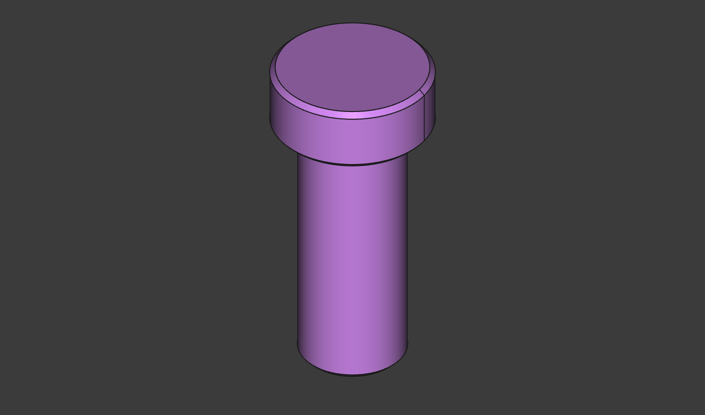
Start by making a screw-like shape. I used two cylinders with the following properties.
AdditiveCylinder- Radius = 15
- Height = 12
- Attachment = Base XY plane
AdditiveCylinder001- Radius = 10
- Height = 50
- Attachment = Base XY plane
- Flip sides = true
Finish it up by putting some 1 mm chamfers on it. We’ll skip the threads. That’s a topic for another tutorial. We’re just going to focus on knurling the head.
Step 2: Square Groove Sketch
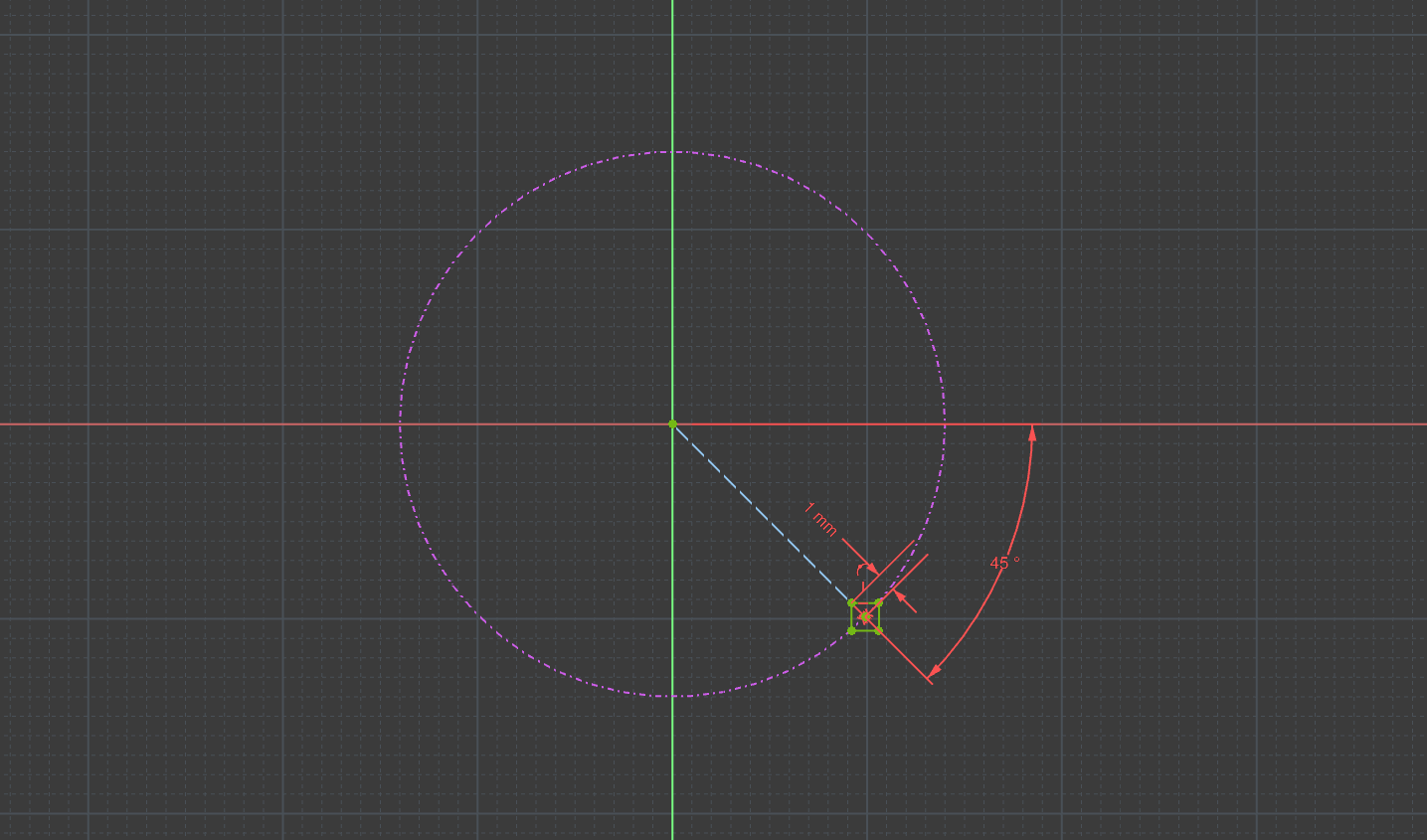
The next step is to sketch the profile of the knurl groove, which we will use in two subtractive helix features. Create a sketch on the XY plane:
- Import the outer diameter of the screw head.
- Draw a construction line from the origin to the diameter, 45-degrees from the X-axis.
- Draw a centered rectangle on the endpoint of the line and coincident to the circle. And make one of the corners coincident with the line.
- Dimension from the rectangle 1 mm from the center to the corner.
Step 3: Subtractive Helix
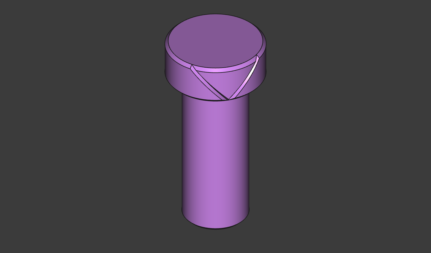
Use this sketch to create two subtractive helix features.
SubtractiveHelix- Axis = base Z axis
- Mode = height-turns-angle
- Height =
f(Cylinder.Height) - Turns = 0.125
SubtractiveHelix001- Axis = base Z axis
- Mode = height-turns-angle
- Height =
f(Cylinder.Height) - Turns = 0.125
- Left handed = true
You may run into an error (as I did) about the base shape being invalid for a Boolean. This is probably because the chamfer is too big, or your square is too big. Try adjusting the size of the chamfer and trying the helix again. If that doesn’t work, the way I got around it was by suppressing the chamfer feature, applying the helix, then un-suppressing the chamfer. Which works for some reason. Maybe it’s a bug. Don’t be discouraged. FreeCAD is getting better every week!
Step 4: Polar Pattern
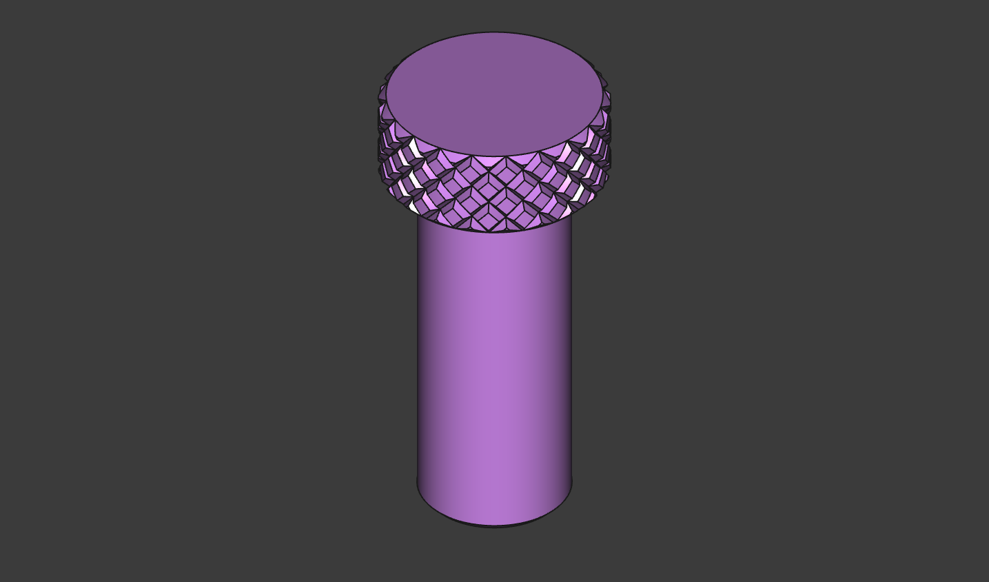
Now use both helix features in a polar pattern. Adjust the number of occurrences to get the knurl looking the way you want. Be patient! When FreeCAD starts recomputing the model, it will seem like the program has frozen. It hasn’t. While this method is overall, a very fast way to create a decent looking knurl, It’s not fast to compute. Depending on the number of occurrences you set, it could take several minutes to compute.
PolarPattern- Transform tool shapes
- Features:
SubtractiveHelixSubtractiveHelix001
- Occurrences = 20
Conclusion
Now you’ve got a knurl! That’s all there is to it. This technique is useful if you want to produce a knurled surface on a 3D printed part. It is not necessary to model the knurl for CNC machined components. An annotation on the drawing will suffice for that.
I have found this to be the simplest, quickest way to get a knurl on a round body. However, the use of polar pattern in this way does require a lot of CPU cycles. Having many such parts in a large assembly could slow things down considerably.
If you want to download and view the file I created, you can get that here:
Transclude of knurltutorial.fcstd
If you like FreeCAD, don’t forget to support the project!