A turned profile feature—the cornerstone of designing parts like shafts, pulleys, and bottle shapes—is typically produced in parametric CAD software by sketching half the profile and revolving it around a central axis.
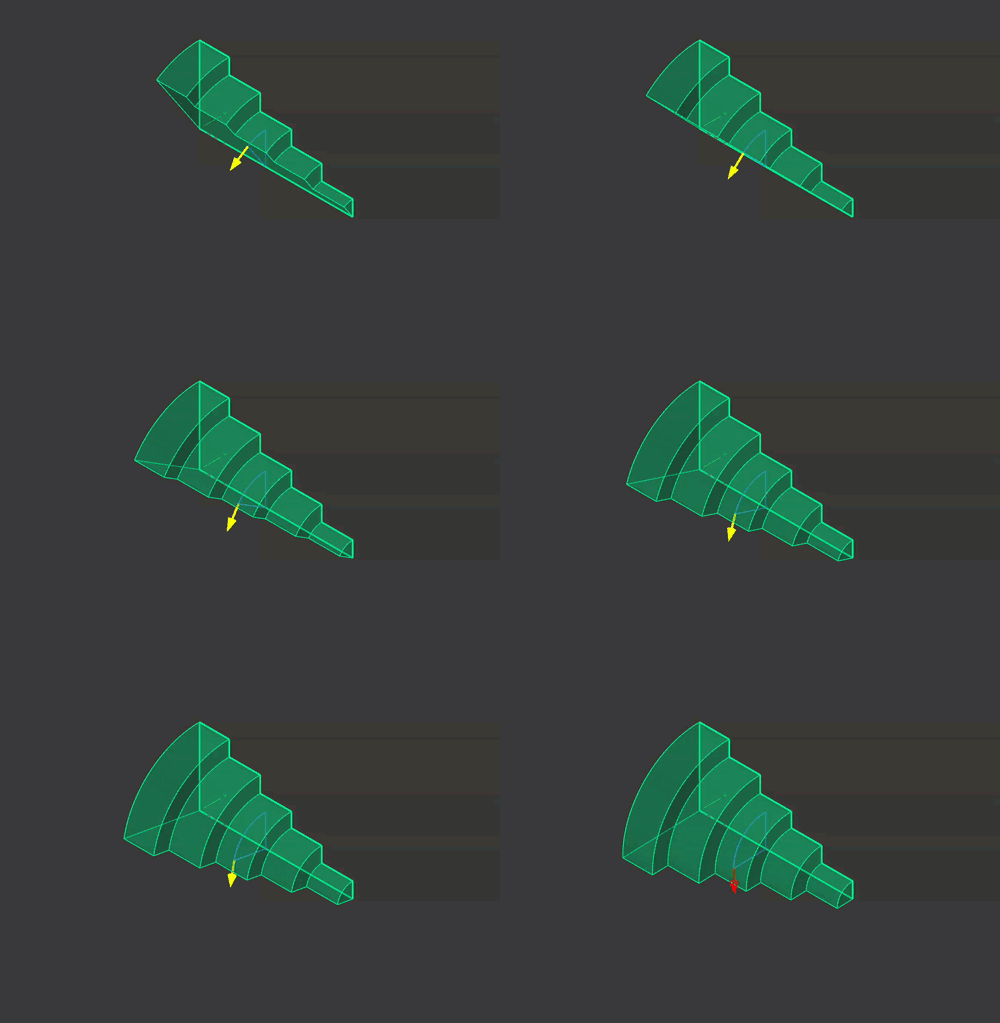
When designing round parts, you’re almost always thinking in terms of diameters, not radii. Being able to input diameters directly into your sketch speeds up your workflow and cuts down on the mental overhead!
In some commercial CAD packages (like SolidWorks), there’s a neat trick: when you dimension a point and move your mouse over the axis of rotation, the dimension automatically snaps to a symmetric point, instantly creating a diameter dimension. This makes constraining something like a multi-diameter shaft quick and intuitive. And if you spend a lot of time around lathes, like me, thinking in diameters is simply more natural, even at the sketching stage.
FreeCAD doesn’t have this auto-snap feature (yet!), but don’t worry! With this simple, powerful trick, you can easily dimension diameters in your revolved profile sketches.
Step 1: Sketch Your Profile
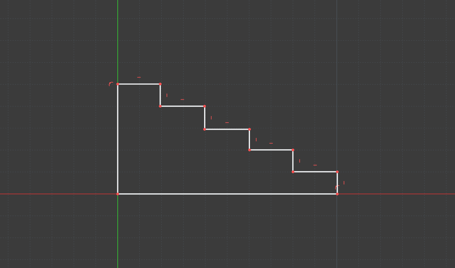
Sketch your revolved profile. Here, I’m creating a short shaft with 5 diameters.
Step 2: Add Symmetry Points
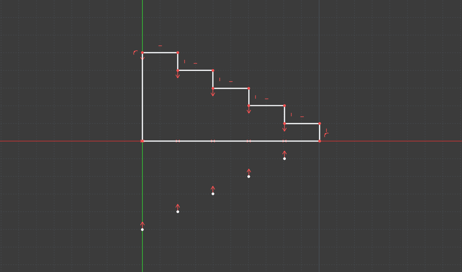
This is the secret sauce in this technique. We’ll use a series of points with symmetry constraints to mimic diameters.
- Add new points to your sketch (
G, Y). Place one point roughly in line with each diameter shoulder on your profile. You need one point for each diameter you want to constrain. - Select the Symmetry Constraint tool (
S). - For the first constraint, click on:
- The point on the profile line.
- The point on the opposite side of the rotation axis.
- The rotation axis line.
- This constraints the points to be symmetric across the axis line. Repeat this for each pair of points along the profile.
Step 3: Constrain the Diameters
With our points all locked in perfect symmetry across the axis, we can now define the diameters.
- Select the Dimension tool (
D) - Click a point on the profile.
- Click the corresponding symmetric point you added in step 2.
- Add your dimension value. This now represents the diameter of the feature, not the radius!
- Exit the sketch and use the revolution tool to create your new feature.
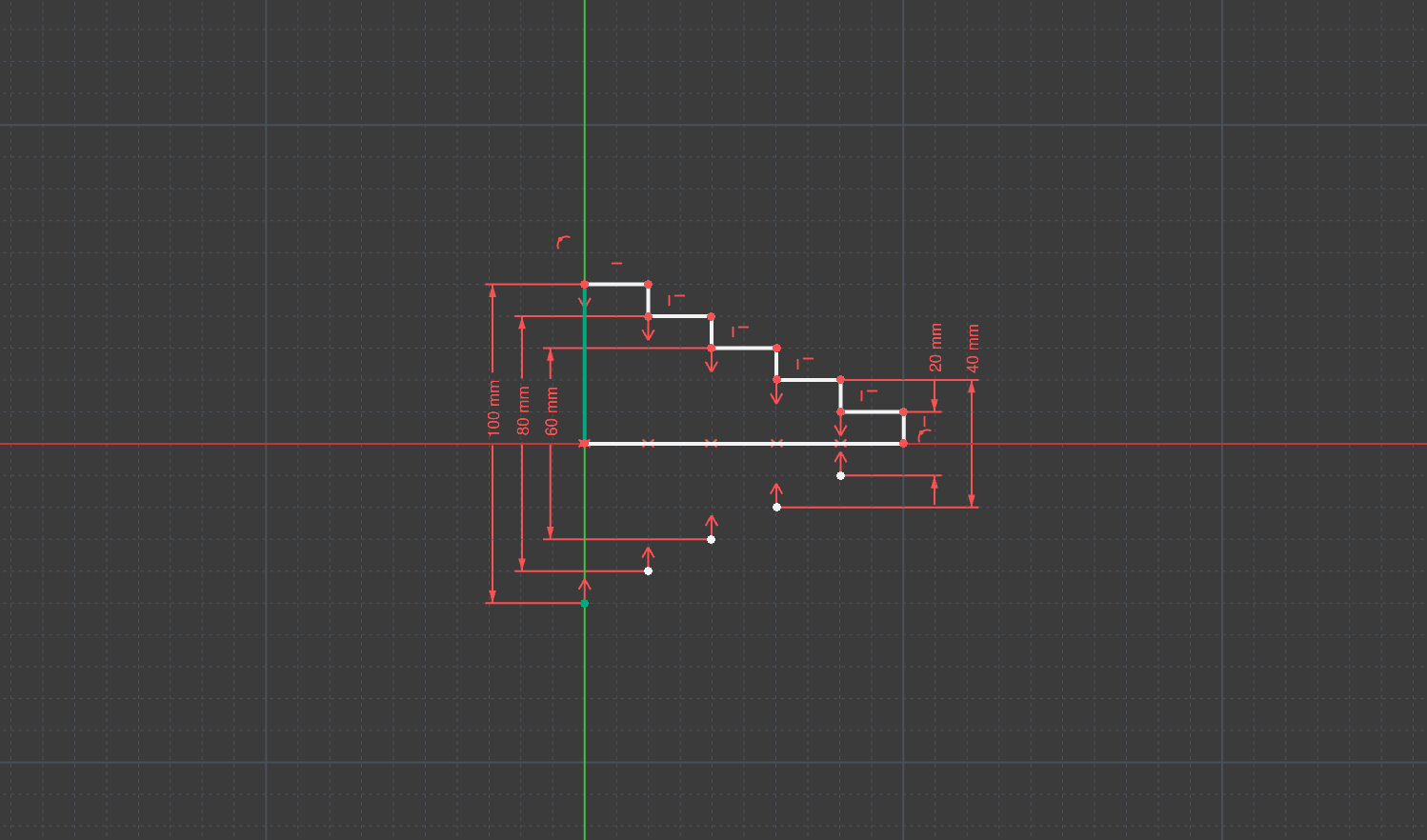
By constraining your sketch with diameters, you eliminate a layer of calculation, making it easier to reference these values in later features (like holes or tolerances) and speeding up your design process. As a machinist, I find this approach is just plain easier when designing anything round.
Conclusion
That’s it! I hope this trick saves you time and headaches in your future designs. If you enjoy using this fantastic tool, please consider supporting the project! Open-source CAD software like FreeCAD is a powerful catalyst for global innovation, removing financial barriers and empowering makers, small businesses, and engineers globally, particularly those in resource-constrained and developing regions.